Geotechnical Engineering
Design that works.
Gateway Geotechnical, providing quality design and construction services since 2006, became a part of THD Design Group, Inc. in 2017. Our experience throughout the region continues to be noteworthy across a broad spectrum of projects, some of which are listed below.
Public Buildings
- St. Louis Art Museum Expansion
- Lafayette Industries North
- Danforth Plant Science Center
- Worldwide Technology Facility
- Support Dogs Headquarters
- Multi-story Clayton Office, Retail, Garage
- St. Louis Cold Drawn Expansions
- Jefferson Barracks Buildings 51 and 52

Municipal
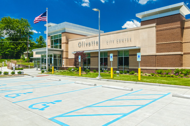
Roadway, Bridge, Utility, or Recreational Facilities for Olivette, St. Peters, Hazelwood, Festus, Marthasville, Washington, St. Ann, University City, Wildwood, Chesterfield, Ballwin, Des Peres, Maryland Heights, and Manchester.
Commercial
- Total Access Urgent Care Facilities (12 to 15 locations)
- American Eagle and Neighbors Credit Unions
- Strip centers and retail facilities such as Dollar General and Walgreens
- Restaurants such as White Castle, Starbucks, Andy’s Frozen Custard, and Arby’s
Schools and Churches
- Elementary and High School Additions for Pattonville, Rockwood, Bayless, and Festus School Districts, and the Miriam School
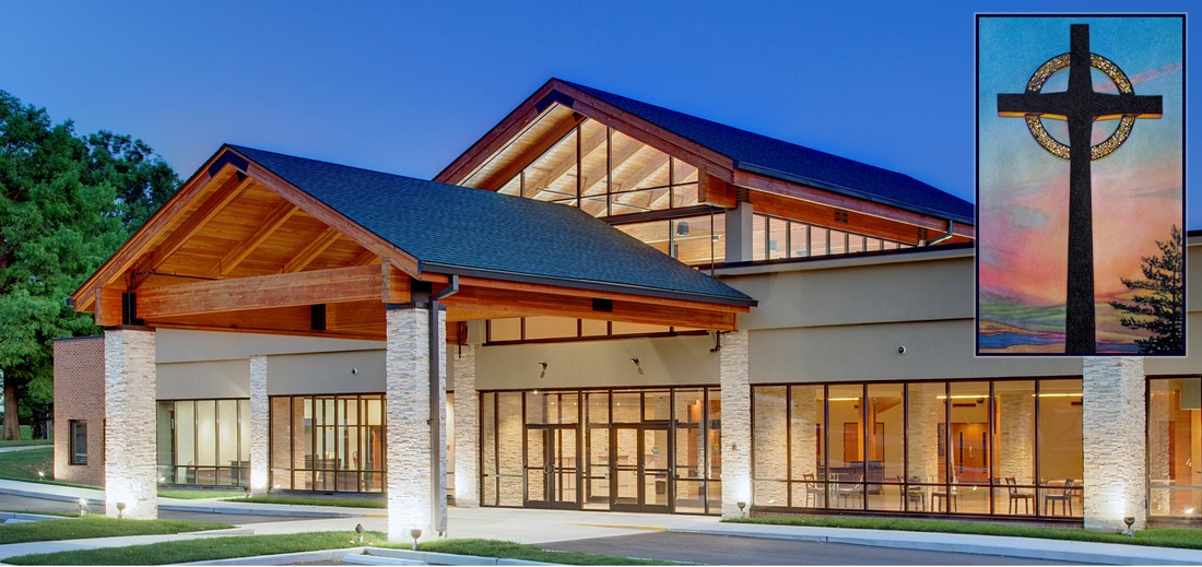
- Church additions for the Archdiocese, and for multiple architects and faiths throughout the region.
Residential
- Multiple single-family developments for Benton Homebuilders, Whalen Custom Homes, Houston Homes; and custom one-of-a-kind estates.
- Multi-Family and Healthcare Facilities such as Waterford, and Maplewood-Richmond Heights and Wellston Child Care Centers.

Selected technical articles from earlier Gateways newsletters follow. Note that their accuracy reflects the State of Practice when published, and that any contained recommendations must be reviewed with respect to more-current regulations and guidelines.
- VEGETATIVE INFLUENCE
- WHAT IS A SHRINKAGE FACTOR? WHY DO I WANT TO KNOW?
- CAN I BUILD ON A SINKHOLE?
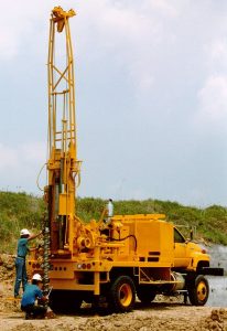
- HOW MANY BORINGS DO I NEED?
- HOW DEEP SHOULD THE BORINGS BE?
- URBAN FILL – What is this stuff and what can I do with it?
- SPRING IS HERE – COMPACTION GUIDE
- DETERMINING THE SEISMIC SITE CLASS
Additional technical articles, biographical summaries remembering local civil engineering leaders (James Pugh Kirkwood, James Buchanan Eads, Charles Shaler Smith, Robert E. Lee, Guy Dufosset, and Henry Flad), as well as numerous general interest and entertaining articles are available.
VEGETATIVE INFLUENCE (Gateways, Winter 2007)
A funny thing has happened over the past 20 years: we have transitioned from initial disbelief, through periods of learning, to total 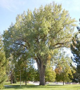 acceptance of the problems trees and heavy shrubbery can cause otherwise well designed and built structures. It usually starts with a call something like, “We’ve been in this building 15 years without any problem, and now the floor slab is cracking and settling. What’s going on?”
Cutting to the chase, the culprit may be drying of cohesive foundation soils resulting from the water demand of nearby vegetation, subsequent shrinkage of the soil, and then the floor slab (and sometimes foundations) moving down with the shrinking soils. There are lots of hard-to-define variables, like the plasticity of the soil; climatic conditions (yes, our recent drought periods have worsened the problem); and the type and age of vegetation and scope of its root system (trees that were planted 20 years ago are now among the biggest offenders). Sometimes we have created our own problems by planting “close to the house” and liberally watering until our trees were old enough to fend for themselves.
So what’s a person to do? Initially crack monitoring or level surveying, preferably over a period of seasons, and a relatively modest geotechnical exploration to define soil conditions and moisture variations are beneficial. If nearby vegetation is a likely cause, several solutions are available. Obviously the easiest answer is to cut down the trees – not a very popular recommendation, especially in these “green” times. Less effectively, you can robustly trim back their canopy in an attempt to reduce their need for water. Another possibility is to provide an artificial barrier between the tree’s roots and the building (count on the roots reaching out well beyond the tree’s dripline). Another “solution” used in the past was supplementary watering via a series of recharge wells installed around the building perimeter, which of course required the owner to fill the wells from a garden hose on a regular basis. We specifically do not recommend this – can you imagine explaining the recurring ritual to neighbors and real estate agents?
Sometimes cutting down the offending trees is not so bad. On a recent project, where settlement of several inches was observed, our analyses led to this recommendation. And the owners were happy to do away with maintaining numerous, closely spaced, 50-foot-tall trees spreading their leaves every Fall. Recent re-inspection of the earlier damage has shown no additional movement through several seasons following felling of the trees. Now, re-leveling of the floors and other cosmetic repairs can be made with increased confidence that the movement has essentially stopped.
WHAT IS A SHRINKAGE FACTOR? WHY DO I WANT TO KNOW? (Gateways, Winter 2008)
At our seminars we often ask what subjects we should include, and one that keeps coming up is the Shrinkage Factor. If you “google” the term, you will find that almost every facet of our society has its own Shrinkage Factor, typically defined in some way as the “percentage by which an output falls short of the estimated or planned output” with the loss due to such things as recording errors, pilferage, spoilage, theft, or wastage. In our case, we just want to know the balance of cut and fill on a site being developed. And that can be simplified by knowing how much a soil or rock shrinks between its natural pre-cut borrow and its in-place compacted conditions. Because of ease of usage or because we just don’t know, we have traditionally used 15% shrinkage. But could we do better either to improve our competitiveness or to increase our profits?
The proper way to determine a Shrinkage Factor is to mathematically compare the material’s density in its natural state with its compacted density. But this requires a reasonable number of undisturbed samples from the borrow area, and a laboratory Proctor test on a representative sample of the same material (e.g., 100 pcf in place at the borrow source and 118 pcf placed at the specified compaction percentage equals approximately 15 percent shrinkage). Obviously, this can be time and cost consumptive, and we usually don’t have the luxury of the needed information. Or maybe the project just isn’t big enough to warrant obtaining it.
We usually make an estimate based on our own experience. However, Horace K. Church’s Excavation Handbook provides an array of choices, based on his compilation of laboratory and field experience. Some of these, specifically for the locally prominent soil and rock types are provided in the following table. Positive percentages indicate shrinkage, negative percentages indicate swell.
Clay 7 to 13%
Silt 11 to 23%
Sand 7 to 15%
Gravel 2 to 9%
75% Soil, 25% Rock 5 to 11%
50% Soil, 50% Rock 3 to 7%
25% Soil, 75% Rock -8 to -16%
Shale -22 to -44%
Limestone -24 to -48%
We suggest that this information provides a good starting point for estimating shrinkage; but, of course, you have to use your own discretion in its use. So, after all this, 15% shrinkage seems to be a pretty good guess for most of our local soils.
CAN I BUILD ON A SINKHOLE? (Gateways, Fall 2010)
Before answering that question, we need to know a little about 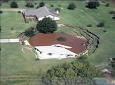 what causes sinkholes, and where we might most likely encounter them in the St. Louis area. Sinkholes are bowl-shaped surface depressions that drain internally. They can be caused simply by collapse due to the weight of material overlying a natural or man-made void or cavity, such as those we see on the morning news where a street has suddenly fallen into an old, decaying, sewer line. More commonly and less dramatically, and of more interest to the developer of a project site, the depression has been caused by movement of overlying soils (by gravity or solution) into fracture features in the underlying limestone. These fractures may have become enlarged over a long period of time, due to solubility of the rock (and karst topography develops).
The latter condition can occur almost anywhere in the St. Louis area, but there are areas where sinkholes are more commonplace. The City of St. Louis south of I-64, in north county along Sinks Road (now that’s a surprise), and along Lindbergh Boulevard in south county are among the known sinkhole areas. Tilles and Carondelet Parks provide good examples of sinkhole topography.
To repair a sinkhole such that it can be built on, it must be excavated down to the top of weathered limestone and the solution channel (fissure, opening, or throat, typically larger than 1 to 2 inches in width) exposed. Depending on the size of the sinkhole, both laterally and in depth, this excavation can be quite large. If the sinkhole is not part of an area-wide drainage system, it can simply be backfilled, typically by placing larger stone across the opening and then covered with progressively smaller stone and capped with a drainage fabric to form a filter; or with a grout or concrete cap to effectively seal the opening. Then the excavated soil can be replaced with controlled compaction up to grade.
If the sinkhole is outside of the building footprint, and actively draining water from the area, the drain should “remain in service,” and the treatment is a bit more complex. The sinkhole can’t simply be filled with grout or concrete, but a filter in combination with a drop inlet or other drainage structure can be placed over the opening. Optionally, the sinkhole can be “taken out of service” by channelizing water collected from the drop inlet to an adequate natural discharge point, such as a ditch or creek.
St. Louis County requires that excavation and/or treatment of sinkholes be authorized by issuance of a grading permit, and inspection to determine if the sinkhole is functioning with regard to drainage. The entire repair operation must be inspected and approved by a qualified geotechnical engineer – that’s us. If the sinkhole is within 10 feet of a public road right-of-way, it must also be inspected by the Department of Highways and Traffic, prior to treatment. Otherwise, the inspection is by the Department of Public Works.
Recently, a Karst Preservation District in north county’s Old Jamestown area has been established by St. Louis County, with the goal to preserve that karst region in its natural state while allowing restricted development. Section 1003.109 of the County’s Design Criteria Manual specifically identifies permitted and conditional land uses, and outlines the geotechnical engineer’s role in the development process.
HOW MANY BORINGS DO I NEED? (Gateways, Winter 2011)
The answer to this question is quite simply “all over the place.” But to arrive at a site-specific answer, we’ll ask the following questions.
What are you building? Where are you building it? Who are you building it for?
 For vertical construction structures such as buildings or industrial facilities (as opposed to horizontal construction of levees, roadways, and utility lines, for example), the first question includes the footprint size and shape, structural loadings if available and special features, importance of the structure and budget constraints, and the desired performance of the completed project. Generally the larger and/or more irregular the footprint, the number of borings should be increased. Special features, such as elevator pits, may require additional borings. With increasing importance of the building and increasing budgets, additional borings may be included.
The second question includes the anticipated subsurface conditions – this is where your geotechnical engineer’s experience and judgment come into play. If the subsurface conditions are anticipated to be relatively poor and variable, more borings should be drilled. Also, if you have any historical background on the site, that should be provided to us (such as fill that might have been placed and tested, or previous improvements that may have been removed).
The third question takes into account any specific requirements of the owner, or possibly the applicable building code or jurisdiction where the project will be located.
There have been many “rules of thumb” for estimating the number of borings required. HUD has required one boring for every 2,500 square feet (footprint) for spread footing supported buildings and one boring for every 1,600 square feet for buildings on deep foundations – of course, you might not know which foundation type is more appropriate until after drilling the borings. And there is no indication as to required depth, so sometimes we have seen a lot of shallow and relatively useless borings proposed for these projects. Some of the “big box” stores have required borings on a 50-foot square grid in the building area – that’s a lot of drilling for a store with as much as an acre under roof – and on a 100-foot square grid for the parking/roadway area. For smaller buildings, some rely on one boring in each corner and maybe a fifth in the center of the building area, or similar coverage.
If we are free to determine the number of borings we usually start with one boring for about every 5,000 square feet of planned footprint, and spaced no more than 80 to 100 feet apart in any direction. The borings should essentially encompass the entire building area so as to eliminate the need to extrapolate subsurface information; and typically a minimum of two or three borings per site, unless the planned project is very small. For larger manufacturing or warehouse buildings, we can usually reduce the number of borings, maybe to one every 6,000 to 8,000 square feet, especially if we expect relatively uniform subsurface conditions – all tempered by our past work in the area.
Many of the same considerations are applicable to horizontal construction. Depending on the complexity of the project, one boring every 300 to 500 feet may be adequate, depending on the variability of the subsurface soils. Additional borings are required at specific features such as major culvert crossings, and maybe as required to define the subsurface conditions along a cross section. State Departments of Transportation may require borings as close as 100-foot spacing along roadways and ramps; and, of course, at least one boring for every abutment and pier unit for bridges.
What’s right boils down to the geotechnical engineer’s experience and judgment, the flexibility given to adjust the field exploration in progress, and ultimately the level of risk accepted or defined by the owner. Typically, more borings result in better recommendations, smoother construction, and reduced life-cycle cost; all with relatively little cost for the additional exploration.
HOW DEEP SHOULD THE BORINGS BE? (Gateways, Spring 2011)
Last issue we discussed how many borings were needed; this issue we’ll kick around how deep they should be drilled. And the answer is “just deep enough” to address all of the project’s design issues or, said a different way, “sufficiently deep to identify all pertinent materials.” And, again, the following two questions need to be addressed:
What am I building?
Where am I building it?
For vertical construction such as buildings or industrial facilities, answers to the first question include the type of construction planned, whether or not there are below-grade levels, and the magnitude of the associated structural loadings. Special features such as elevator pits, detention basins, retaining walls, and slope stability need to be considered as well.
We can all readily agree that the borings should extend deeper than the lowest planned construction. One rule of thumb says to drill at least twice the maximum footing dimension below the planned bearing level, so that supporting materials throughout the depth of greatest influence are characterized. For slab-on-grade buildings with minimal cut and fill, and where the loadings are not great, say a one or two-story, wood-frame building, 15 feet may be enough. On the other hand, if this building has a below-grade (basement) level, a 15-foot boring would provide little to no information for the bearing materials – you’ll need at least a 25 to 30-foot boring to obtain the same design information.
Addressing the second question should consider the local geology and anticipated subsurface conditions; and maybe the need for intermediate or deep foundations. If the loads are relatively high or concentrated, such as for multi-story buildings, parking garages, or bridges; and/or the structure is located in an area of suspect support, the borings will likely have to be extended deeper – to depths of 40, 50, or more feet, or perhaps to bedrock (essentially zero to 100 feet or more in the St. Louis area). If there is a need to take advantage of the higher bearing values bedrock can provide, its coring may be required. Drilled piers in this area are typically designed for a bearing value of 20 kips per square foot (ksf) of end area at practical refusal (no rock coring required), up to a maximum of about 100 ksf for sound bedrock verified with coring.
Another reason for deeper borings is the development of an appropriate Seismic Site Class, which is based on the IBC code adopted by local jurisdictions. At least one boring needs to characterize the subsurface conditions down to 100 feet, or to a lesser depth which would define the assigned class. Usually, because of uniform deposits of soft materials or encountered bedrock, this can be accomplished after about 50 or 60 feet of drilling. Sometimes on smaller projects, clients view it economically advantageous to accept a less favorable class without implementing deeper drilling. To make the right decision, the geotechnical engineer needs to understand his client, and to be in close communication with his drillers as the exploration is progressing.
Many of the same considerations are applicable to horizontal construction. For utility lines, roadways, and other site development, borings need to penetrate the full depth of cut plus at least 5 feet; and in fill areas borings should extend to a depth at least equivalent to the height of fill plus the thickness of any soft or otherwise compressible materials encountered.
Again, what’s right boils down to the geotechnical engineer’s experience and judgment, the flexibility given to adjust the field exploration in progress, and ultimately the level of risk accepted or defined by the owner. If in question, always drill a little deeper – the nominal extra cost of 5 or 10 more feet will keep you out of trouble more often than not.
URBAN FILL – What is this stuff and what can I do with it? (Gateways, Fall 2012)
There’s good fill and, well, not so much. Good fill is, at its best, clean  low plastic material, placed in thin lifts with controlled moisture and compactive effort commensurate with its intended usage. Lesser fill may have been “tracked in” or otherwise placed with little more concern than just filling up space.
Uncontrolled fill is relatively common, and can be encountered anywhere – maybe even places where future site development was never considered. The obvious treatment is removal and replacement, with either the acceptable materials going back into place with control, or new approved material being brought on site. A more onerous situation occurs with “urban fill,” a term we use to describe fills placed primarily as a part of urban renewal – A building is torn down and the construction debris is pushed into the basement excavation and covered up to look nice at the surface. Or maybe it’s just dumped bedsprings, glass jars, and telephone books. If such situations are not identified during the geotechnical exploration phase, they pop up as a “surprise” during construction. Building in rehabbed areas should be the first clue that urban fill may become an issue.
So, here’s what you need to do. First remove all undesirables down to natural materials, beneath the footprint of the new construction plus a surrounding area equal to the height of the fill removed. Undoubtedly there will be an old floor slab at the base of the excavation – it should also be removed or, at a minimum, broken or drilled through at numerous locations to prevent collected ponds of infiltrating water that could soften the bearing materials. Basement walls or other mass concrete can usually be left in place provided it has good bearing and is broken off two to three feet below any new construction. The undesirables that have been removed have no place to go except to a legal off-site dump. Then the excavation can be brought up to the desired grade with properly compacted and controlled fill.
In less critical areas, where the owner accepts increased maintenance associated with settlement, and potentially re-orientation of existing fill, a portion of the undesirable fill – say three feet or so – can be removed, the base of the overexcavation proofrolled, and properly compacted controlled fill brought up to grade. This really can be tolerated only if the fill consists of non-decayable construction debris (bricks, concrete, metal, no wood). This less-than-desirable approach is seldom satisfying in the long term, but may be economically acceptable.
SPRING IS HERE – COMPACTION GUIDE (Gateways, Spring 2014)
 Groundhog Day has come and gone. What was he looking at? Was it his shadow, or maybe the passing of construction equipment waking him from hibernation? Yes, some earthwork is underway. And along with that operation, compaction of fill still remains a mystery to many of us. Hopefully we can answer some of those FAQs.
Q. What is soil compaction?
A. It’s the process of making the soil denser by pushing the solids and water closer together, occupying previously void space. The result is a denser, more capable soil.
Q. How hard do I need to push (aka, what degree of compaction is required)?
A. It depends on what you’re planning to build. Typically we see required compaction of 90 or 95 percent of the soil’s maximum dry density (Proctor value) for support of spread footings.
Q. How many Proctor tests do I need?
A. Since different soils react to compactive effort in their own unique way, you really need a Proctor for each distinct type of soil that will be used as fill. The Proctor curve, which resembles an inverted parabola, relates moisture content on the x-axis and corresponding dry density on the y-axis.
Q. But is that a Modified or Standard Proctor? Does it matter?
A. Yes and yes. Both tests are used in the local area, with the modified version providing roughly 4½ times the compactive energy of the Standard. A couple of things to remember – first, the Modified curve is typically lower in moisture content and higher in dry density than the Standard curve and, second, it’s not a good idea to mix the two on any single project. Most important, it doesn’t really make much difference which you use, as long as the required percent compaction and the planned performance of the compacted soil are compatible with each other.
Q. What’s this relative density specification I sometimes see?
A. Relative density should be used as a compaction requirement for fairly clean granular soils – sands – that may not exhibit the typical Proctor curve. You can always tell who doesn’t know their compaction (or maybe who doesn’t read our Geotechnical Reports) when relative density requirements are used for cohesive soils – clays and silts. Or when relative density values similar in magnitude to Proctor numbers are called for. A relative density on the order of 70 percent is usually appropriate beneath spread footings, with an end-dumped and tamped 50 percent good enough elsewhere.
DETERMINING THE SEISMIC SITE CLASS (Gateways, Summer 2018)
The thing that seems to concern us most these days with our geotechnical exploration clients is the seismic site class. Here’s what we hear. Is my Seismic Site Class a “C” or a “D” (or worse)?
I’ve got to have a “C.”
What can I do to change your recommended “D” to a “C?”
And rightly so, as there is confusion on how it is determined and often times a major impact on design and the cost of construction.
First off, like the weatherman, we are only the messenger – interpreting the results of our exploration, not being the creator of what or why. That said, let’s take a look at how we determine our recommended Seismic Site Class by example, using the following subsurface stratigraphy, typical for some areas in and around St. Louis.
| Soils | Depth (feet) | Thickness (feet) | SPT (N value, bpf) | Undrained Shear Strength (psf) |
| Silty clay | 0 to 5 | 5 | 12 | 1,500 |
| 5 to 15 | 10 | 7 | 750 | |
| 15 to 20 | 5 | 10 | 1,250 | |
| Clay | 20 to 30 | 10 | 17 | 2,000 |
| Bedrock | @ 30 | – | 50/2 inches | – |
Using formulas (reference International Building Code Section 1613 and ASTM 7-10 Chapter 20) based on the Standard Penetration Test (SPT), the weighted N value for the top 100 feet equals 100/ (5/12 +10/7 +5/10 +10/17 +70/100 maximum allowed for bedrock) or 28 blows per foot (bpf). This would be classified as “stiff soil” with a Seismic Site Class “D“ because the weighted N value falls between 15 and 50 bpf. This apparent conservatism may be due to the lack of confidence the developers of the above-referenced documents may have had in the SPT as a measure of soil resistance? It must be noted that the less-than-50 bpf value above is largely due to the softer layer encountered from a depth of 5 to 15 feet; such softer layers are often what keep sites from achieving a “C” Seismic Site Class.
In lieu of the above method, the Seismic Site Class can be determined using undrained shear strength values from laboratory unconfined compressive strength or triaxial tests (not pocket penetrometer values). The weighted undrained shear strength for the top 100 feet equals 100/ (5/1,500 +10/750 + 5/1,250 +10/2,000 +70/5,000 maximum allowed for bedrock) or 2,500 psf. This would be classified as “very dense soil and soft rock” with a Seismic Site Class “C“ because the weighted undrained shear strength is more than 2,000 psf. Although a little more favorable result (compared to using just SPT data) can be anticipated in some but not all cases, we seldom (almost never?) have enough testing, which is limited by the cost of initial exploration, to have confidence in this method and to take its advantage.
Finally, shear wave velocity testing using Multichannel Analysis of Shear Waves (MASW) or Refraction Micrometer (ReMi) methods can be used in lieu. Based on our local experience, and serving as an indication of the higher level of confidence of the developers of the above-referenced documents (?), the Seismic Site Class can normally but not always be increased from a “D” to a “C.” Or maybe even an “E” to a “D” (except in deep alluvial deposits in our river or abandoned tributary valleys). We utilize this method frequently to supplement calculations using SPTs, coordinating with Dr. Neil Anderson with the Missouri University of Science and Technology, who serves as our primary interpreter of the obtained field data. Its cost can easily be repaid many times over during construction, and should certainly be considered beneficial for taller buildings or other unusual structures.